Antes de nada, agradecer a Braineack de mt.net por este How-to. Me voy a limitar a hacer una traducción del texto:
EDIT: Voy a ir rellenando los espacios con el texto en ingles, despues cuando vaya teniendo tiempo ire traduciendo
COSAS QUE NECESITAS SABER ANTES DE TURBOALIMENTAR TU MIATA
1. CONTROL DEL ENCENDIDO
Hay en realidad tres modos de reducir la probabilidad de predetonación a plena carga en un
motor con turbo: reducir el boost, ajustar el AFR a mezcla más rica, y retardar el
encendido. Estos tres parámetros tienen que ser optimizados juntos para conseguir la
potencia fiable más alta. ¿Que es la predetonación? El asesino de motores.
Sin no se instala ningun tipo de controlador de encendido el valor base "seguro" recomendado
son 6º (8º si usamos un intercooler) . Y esto es sólo si ningún sonido de picado está
presente. Esto por lo general privara de par motor en la parte baja del cuentarevoluciones y
reducira toda la linea de par/potencia hasta el final.
El Bipes ACU retrasa dinamicamente el encendido para evitar predetonación. Bipes ACU usa
tres parámetros de entrada para controlar el encendido: flujo de aire, REVOLUCIONES POR
MINUTO, y Temperatura de admisión. Puede retrasar un total de 14 ° de encendido. No sólo va
a ayudar a proteger contra la detonación, tambien se devuelve la potencia en bajos si se
mantiene el encendido base en 10* o mas avanzado. El Bipes es un dispositivo probado en
Miatas NA, turboalimentados y compresorizados. Las ECU "standalone" y las "piggyback"
implementan esto como función.
Otra opción es la "MSD Boost control" expresamente diseñada para el Miata. El Bipes en
realidad es un mod de esta unidad pero con mas ajuste. Ambos se pueden comprar aun, pero el
precio es similar para ambos. La MSD retarda el encendido 3 ° por psi de soplado, retrasando
un total de 6º como mucho.. Cuando no hay presión presente, El encendido vuelve a funcionar
de serie. Con esto, todavía se puede controlar el motor avanzado a 14 ° de encendido base y
cuando entremos en BOOST retrasará hasta los 8 °. Si la predetonación está todavía presente
entonces tendriamos que retrasar el encendido base un poco. Es un mecanismo basico, pero
hace el trabajo bien.
La tercera y mejor opción es una centralita "aftermarket" o un dispositivo piggyback, estos
te dan control completo sobre el mapa de encendido, basandose en carga y revoluciones.
Como sobrealimentar un Miata, facil y para toda la familia!
Moderador: Moderadores
-
ismael_pt

- Mazdaspeed

- Mensajes: 1961
- Registrado: 16 May 2009, 16:44
- Ubicación: entre palmeras
- Contactar:
Como sobrealimentar un Miata, facil y para toda la familia!
Última edición por ismael_pt el 16 May 2009, 21:39, editado 3 veces en total.

-
ismael_pt
- Mazdaspeed
- Mensajes: 1961
- Registrado: 16 May 2009, 16:44
- Ubicación: entre palmeras
- Contactar:
2. Regulador de presión de gasolina ajustable (AFPR: adjustable fuel pressure regulator)
Un turbo incrementa la densidad del aire, como resultado obtenemos una mezcla mas densa. Esta mezcla mas densa eleva el pico de presión de los cilindros, incrementando la posibilidad de predetonación.A la vez que el AFR (air-fuel ratio) queda pobre, la temperatura de los gases quemandose se eleva, lo que tambien aumenta la probabilidad de predetonación. Por esto es imprescindible llevar un AFR mas rico en un motor sobrealimentado cuando vamos a plena carga. Haciendo esto reduciremos la probabilidad de predetonación, y tambien mantendremos las temperaturas controladas.
Con lo cual.... cuando turboalimentamos un miata necesitamos mas caudal de combustible fluyendo hacia los inyectores. Por que? Porque los inyectores estan fabricados para dar una cantidad "x" de cc/min de combustible a 43.5psi (3 bares). Esta cantidad puede ser convertida en la cantidad de caballos que podremos lograr. Elevando la presión de combustible en la rampa de inyección, estamos aumentando la cantidad de caballos que podriamos manejar con nuestros inyectores. En resumen, elevar la presion del combustible eleva los cc/min de un inyector! Lo pillais? **Inyectores, ver Sección 3**
Un AFPR (regulador ajustable de presion de combustible) o un FMU (fuel management unit, similar al afpr) son alternativas a la economicamente costosa sustitucion de la centralita. Funciona usando como referencia la presion/vacio del colector de admisión para variar la presion de combustible y elevarla cuando entremos en boost.
El regulador de BEGi esta diseñado para incrementar la presión de combustible en el sistema de inyección aumentando la capacidad del regulador de presión que tiene el coche de fabrica. Este regulador debe usarse en conjunto con el regulador de fábrica, el cual proporciona la base de presión (la presion que hay en la rampa mientras el coche esta al ralentí). La cantidad de presión "extra"puede ser ajustada mediante un tornillo que tiene este aparato en el lateral.
El Vortech FMU trabaja de manera similar al anterior, pero el aumento de presión de combustible esta determinado por un disco que puede ser sustituido. Los diferentes disco son baratos, no obstante requieren desmontar el aparato para cambiar el disco.
Para determinar la cantidad de combustible que puedes proporcionar con tu AFPR o tu FMU se calcula de el siguiente modo:
Presión de combustible en la rampade inyeccion = incremento de presión x boost + presión al ralentí
Ejemplo: 10 x 5 + 50 = 100psi
Con lo cual con un ratio de 10:1 (10psi de combustible por cada 1psi de boost) puedes proporcionar 100psi de combustible a tus inyectores cuando estas soplando a 5 psi. Si no planeas estar cambiando tu cantidad de boost a menudo la opcion de un FMU con un disco estatico, puede resultarte mas barata que un AFPR. De todas formas, el beneficio añadido de poder suministrar y ajustar la presión corrrecta girando un simple tornillo merecen en gasto extra.
-Nota- Inyectores mas grandes, Intercooler, etc., pueden cambiar los niveles de combustible necesitados. Aun asi no es recomendado usar mas de 100-110psi en la rampa de inyección. *Llegados a este punto es hora de pensar en instalar inyectores de mas caudal que puedan servirnos para cifras de potencia mas altas a 100psi o menos de presión en la rampa. La centralita de serie del miata puede manejar un inyector con un 20-30% de mayor caudal. Por lo tanto la gestion de combustible con la centralita de serie del miata no puede llegar mas lejos. Si piensas en superar estos limites, deberias considerar la opcion de un EMS (engine management system, es decir una centralita aftermarket, Megasquirt, Emanage, Adaptronic, etc).
*Ver la sección 3 sobre los inyectores.
Hard Line -> Front of Fuel Rail -> OEM FPR -> OFFSET Fitting of FMU -> CENTER fitting of FMU -> Return Line
99-01+ Lineas de combustible sin retorno! Mirar aqui los interesados.
Tambien se puede hacer, pero tengo que buscar los esquemas de como se conecta, ahora mismo no los encuentro.
Usuarios de EMS ( centralitas aftermarket)
No teneis que preocuparos en cuestiones de incrementar la presión de combustible si teneis una centralita programable. Como el control es completo, simplemente teneis que añadir inyectores de mayor caudal (los que ahora ya podeis controlar) y utilizar el regulador de presión de fabrica. El dinero ahorrado en un AFPR o un FMU, podeis aprovecharlo para comprar unos inyectores mas grandes para llegar a vuestra meta de potencia.
Última edición por ismael_pt el 17 May 2009, 21:22, editado 4 veces en total.
-
ismael_pt
- Mazdaspeed
- Mensajes: 1961
- Registrado: 16 May 2009, 16:44
- Ubicación: entre palmeras
- Contactar:
3. Inyectores
Los inyectores del 1.6 (230cc/min) dan para un margen de 5-6 psi. De todas formas a este nivel, la presion de combustible necesitada para alimentar al motor con estos pequeños inyectores comienza a ser muy alta, tanto que los inyectores podrian quedarse bloqueados. Si vas a desarollar mas de 140-150rwhp, lo mas probable esque los inyectores lleguen a su limite. Una mejora muy comun para los 1.6 es instalar los inyectores del 1.8. Estos dan margen para 7-8 psi (170-180rwhp).
94-97 265cc - #195500-2180
99-00 240cc - #195500-4430
01-05 265cc - #195500-4060
Los inyectores del modelo desde el 99 en adelante estan hechos para mas presión de combustible (60psi) y suelen esparcir mejor el combustible
Lo ideal es poder manejar inyectores mas grandes con una presión de combustible baja, de todas formas sin una centralita que permita controlarlos no es posible. La centralita de serie tiene un poco de margen para manejar inyectores un poco mas grandes, requiere que se ajuste despues el ralentí. La ecu del 1.6 podria manejar inyectores de hasta 330cc. Requeriria ajustar el AFM (caudalimetro que llevan los NA, en los NB es diferente, es un MAF) para calibrar la mezcla en ralentí.
Los inyectores que comunmente se usan con centralitas EMS son los 460cc y 550cc del RX-7. Los 460s dan margen de hasta unos 250rwhp, los 550s alrededor de 300rwhp.
Si estas usando un dispositivo “piggyback” para el control de combustible como por ejemplo E-manage (no es un centralita en si, sigue siendo un piggyback), Los inyectores mas usados suelen ser los 305cc del Supra. Si usas una centralita programble en sustitucion a la de serie, la eleccion mas usada son los inyectores RC 550cc
El Miata usa inyectores de alta impedancia. Tambien conocidos como inyectores saturados.
Complete list of Miata plug and play replacement injectors (“F” connector):
Code:
Year Make/Model Engine Size/Color Part #
87-88 Toyota MR2 4AGE NA 213cc – Beige Top #23250-16080
89-91 B2220 Truck 224cc - Yellow Top? #23250-74040?
99-00 Mazda Miata 240cc - Thin Red Body #195500-4430
Toyota 4AGE 250cc – Green Top
Toyota 4AGE 250cc – Violet Top
94-97 Mazda Miata 265cc - Tan Top #195500-2180
01-06 Mazda Miata 265cc - Thin Lt. Prple #195500-4060
Toyota 3SGE 295cc – Green Top
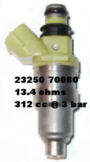
89-92 Toyota Supra 7MGE NA 305cc – LT Green Top #23250-70080
93-95 Toyota Supra 3.0L 312cc - Maroon Top #23250-46030
Toyota 3SGE 315cc – Pink Top
90-92 MX6/626/Probe Turbo 326cc - Gray Top #195500-2150
89-91 B2600 Truck 326cc - Gray Top #195500-2150
Mazda 323 GTX TURBO 360cc - Black Top #195500-2130
Celica/MR2 3SGE NA 370cc - Green Top #23250-74160
Mazda RX8 420cc - Yellow Body #195500-4450
89-92 Mazda RX-7 NA 440cc - Blue Top #195500-5740
89-91 RX-7 NA 460cc - Red Top #195500-2010
89-91 RX-7 TURBO 550cc - purple top #195500-2020
El mismo tipo de conector puede ser encontrado en inyectores de baja impedancia, pero usar inyectores de baja impedancia requiere el uso de resistencias para poder controlarlos.
Direct fit LOW OHM injectors (“E” connector):
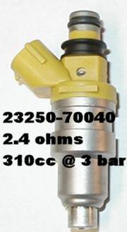
89-92 Toyota Supra (7MGE) NA - (295cc – Yellow Top) - #23250-70040
88-91 Toyota Collora GT-S Turbo (4AGZE) – (365cc – Red-Orange Top)
92-95 Toyota Collora GT-S TURBO (4AGZE) – (365cc – Red-Orange Top)
86-92 Toyota Supra (7MGTE) TURBO – (430cc – Black Top)
Toyota MR2 (3SGTE) TURBO – (430cc – Black Top)
Alta impedancia vs. Baja impedancia.
Eligiendo inyectores:
En la mayoria de los casos un motor turboalimentado requiere un "B.S.F.C" de 0.60. (B.S.F.C es "brake specific fuel consumption"; es decir cuanto combustible esta usando por cada caballo de potencia durante una hora de tiempo. Esto significa que el motor usará 0.60 libras de combustible a la hora por cada caballo de potencia que produce. Usar un valor de 0.55 para el miata parece que es mas preciso para hacer los calculos.
La mayoria de los inyectores funcionan bien hasta el 80-85% del "duty cycle" (el duty cycle es la cantidad de tiempo de trabajo).
Usando estos numeros como guia, puedes elegir el tamaño aproximado del inyector de tu miata para unos 200hp aproximados(al motor) con la siguiente formula:
Potencia estimada x B.S.F.C / nº de inyectores x tiempo de trabajo (duty cycle) = lb/hr por inyector
Para pasar de libras a cc: cc = lb/hr x 10.5
200 x .55 / 4 x .8 = 110 / 3.2 = 34.4 lb/hr x 10.5 = 360cc
Ahora hay que averiguar la presión que tenemos en la rampa de inyección, para determinar que inyector alcanzara el nivel deseado de caudal. Las especificaciones de los inyectores vienen determinadas a 43.5psi de presión en la rampa ( 3 bar ), esta formula determinará que caudal darán a una presión mayor en la rampa:
FUEL PRESSURE / 43.5 = New Flow Rate
Square Root of NFR x Old Flow Rate = New Flow Rate of Injector
A 6 psi con un FMU de ratio 8:1 tendrás alrededor de 96psi de combustible. Usaremos esta formula para encontrar un inyector que tenga un caudal de 360cc @ 96psi:
96 / 43.5 = 2.206
squareroot of 2.206 = 1.485
1.485 x 265cc = 393cc
Esto significa que a 96psi un inyector de 265cc abastecera la necesidad de 360cc (y un poquito mas de margen ) para alcanzar 200 HP (165rwhp).
Por lo tantolos inyectores del 1.8 estaran a menos del 80% de duty cycle a unos 6psi de boost con los 96psi de combustible. ¿Pero que pasa si añadimos mas presión de combustible?. Recuerda que el calculo se hizo con un ratio 8:1 en el regulador de presión FMU. El ratio mas agresivo es 12:1. Veamos como afecta este ratio a los inyectores del 1.6:
12 x 6 + 48 = 120psi of fuel
120 / 43.5 = 2.75
sqrt of 2.75 = 1.65
1.65 x 203cc = 334cc
200 x .55 / 4 x .8 = 110 / 3.2 = 34.4 lb/hr x 10.5 = 361cc
Por lo tanto los inyectores del 1.6 estaran fuera de margen para 200 HP (165rwhp) aun a 120psi de presión de combustible.
Aqui puedes hacer los mismos calculos de forma automatizada: http://www.rceng.com/technical.htm
Los inyectores del 1.6 (230cc/min) dan para un margen de 5-6 psi. De todas formas a este nivel, la presion de combustible necesitada para alimentar al motor con estos pequeños inyectores comienza a ser muy alta, tanto que los inyectores podrian quedarse bloqueados. Si vas a desarollar mas de 140-150rwhp, lo mas probable esque los inyectores lleguen a su limite. Una mejora muy comun para los 1.6 es instalar los inyectores del 1.8. Estos dan margen para 7-8 psi (170-180rwhp).
94-97 265cc - #195500-2180
99-00 240cc - #195500-4430
01-05 265cc - #195500-4060
Los inyectores del modelo desde el 99 en adelante estan hechos para mas presión de combustible (60psi) y suelen esparcir mejor el combustible
Lo ideal es poder manejar inyectores mas grandes con una presión de combustible baja, de todas formas sin una centralita que permita controlarlos no es posible. La centralita de serie tiene un poco de margen para manejar inyectores un poco mas grandes, requiere que se ajuste despues el ralentí. La ecu del 1.6 podria manejar inyectores de hasta 330cc. Requeriria ajustar el AFM (caudalimetro que llevan los NA, en los NB es diferente, es un MAF) para calibrar la mezcla en ralentí.
Los inyectores que comunmente se usan con centralitas EMS son los 460cc y 550cc del RX-7. Los 460s dan margen de hasta unos 250rwhp, los 550s alrededor de 300rwhp.
Si estas usando un dispositivo “piggyback” para el control de combustible como por ejemplo E-manage (no es un centralita en si, sigue siendo un piggyback), Los inyectores mas usados suelen ser los 305cc del Supra. Si usas una centralita programble en sustitucion a la de serie, la eleccion mas usada son los inyectores RC 550cc
El Miata usa inyectores de alta impedancia. Tambien conocidos como inyectores saturados.
Complete list of Miata plug and play replacement injectors (“F” connector):
Code:
Year Make/Model Engine Size/Color Part #
87-88 Toyota MR2 4AGE NA 213cc – Beige Top #23250-16080
89-91 B2220 Truck 224cc - Yellow Top? #23250-74040?
99-00 Mazda Miata 240cc - Thin Red Body #195500-4430
Toyota 4AGE 250cc – Green Top
Toyota 4AGE 250cc – Violet Top
94-97 Mazda Miata 265cc - Tan Top #195500-2180
01-06 Mazda Miata 265cc - Thin Lt. Prple #195500-4060
Toyota 3SGE 295cc – Green Top
89-92 Toyota Supra 7MGE NA 305cc – LT Green Top #23250-70080
93-95 Toyota Supra 3.0L 312cc - Maroon Top #23250-46030
Toyota 3SGE 315cc – Pink Top
90-92 MX6/626/Probe Turbo 326cc - Gray Top #195500-2150
89-91 B2600 Truck 326cc - Gray Top #195500-2150
Mazda 323 GTX TURBO 360cc - Black Top #195500-2130
Celica/MR2 3SGE NA 370cc - Green Top #23250-74160
Mazda RX8 420cc - Yellow Body #195500-4450
89-92 Mazda RX-7 NA 440cc - Blue Top #195500-5740
89-91 RX-7 NA 460cc - Red Top #195500-2010
89-91 RX-7 TURBO 550cc - purple top #195500-2020
El mismo tipo de conector puede ser encontrado en inyectores de baja impedancia, pero usar inyectores de baja impedancia requiere el uso de resistencias para poder controlarlos.
Direct fit LOW OHM injectors (“E” connector):
89-92 Toyota Supra (7MGE) NA - (295cc – Yellow Top) - #23250-70040
88-91 Toyota Collora GT-S Turbo (4AGZE) – (365cc – Red-Orange Top)
92-95 Toyota Collora GT-S TURBO (4AGZE) – (365cc – Red-Orange Top)
86-92 Toyota Supra (7MGTE) TURBO – (430cc – Black Top)
Toyota MR2 (3SGTE) TURBO – (430cc – Black Top)
Alta impedancia vs. Baja impedancia.
Eligiendo inyectores:
En la mayoria de los casos un motor turboalimentado requiere un "B.S.F.C" de 0.60. (B.S.F.C es "brake specific fuel consumption"; es decir cuanto combustible esta usando por cada caballo de potencia durante una hora de tiempo. Esto significa que el motor usará 0.60 libras de combustible a la hora por cada caballo de potencia que produce. Usar un valor de 0.55 para el miata parece que es mas preciso para hacer los calculos.
La mayoria de los inyectores funcionan bien hasta el 80-85% del "duty cycle" (el duty cycle es la cantidad de tiempo de trabajo).
Usando estos numeros como guia, puedes elegir el tamaño aproximado del inyector de tu miata para unos 200hp aproximados(al motor) con la siguiente formula:
Potencia estimada x B.S.F.C / nº de inyectores x tiempo de trabajo (duty cycle) = lb/hr por inyector
Para pasar de libras a cc: cc = lb/hr x 10.5
200 x .55 / 4 x .8 = 110 / 3.2 = 34.4 lb/hr x 10.5 = 360cc
Ahora hay que averiguar la presión que tenemos en la rampa de inyección, para determinar que inyector alcanzara el nivel deseado de caudal. Las especificaciones de los inyectores vienen determinadas a 43.5psi de presión en la rampa ( 3 bar ), esta formula determinará que caudal darán a una presión mayor en la rampa:
FUEL PRESSURE / 43.5 = New Flow Rate
Square Root of NFR x Old Flow Rate = New Flow Rate of Injector
A 6 psi con un FMU de ratio 8:1 tendrás alrededor de 96psi de combustible. Usaremos esta formula para encontrar un inyector que tenga un caudal de 360cc @ 96psi:
96 / 43.5 = 2.206
squareroot of 2.206 = 1.485
1.485 x 265cc = 393cc
Esto significa que a 96psi un inyector de 265cc abastecera la necesidad de 360cc (y un poquito mas de margen ) para alcanzar 200 HP (165rwhp).
Por lo tantolos inyectores del 1.8 estaran a menos del 80% de duty cycle a unos 6psi de boost con los 96psi de combustible. ¿Pero que pasa si añadimos mas presión de combustible?. Recuerda que el calculo se hizo con un ratio 8:1 en el regulador de presión FMU. El ratio mas agresivo es 12:1. Veamos como afecta este ratio a los inyectores del 1.6:
12 x 6 + 48 = 120psi of fuel
120 / 43.5 = 2.75
sqrt of 2.75 = 1.65
1.65 x 203cc = 334cc
200 x .55 / 4 x .8 = 110 / 3.2 = 34.4 lb/hr x 10.5 = 361cc
Por lo tanto los inyectores del 1.6 estaran fuera de margen para 200 HP (165rwhp) aun a 120psi de presión de combustible.
Aqui puedes hacer los mismos calculos de forma automatizada: http://www.rceng.com/technical.htm
Última edición por ismael_pt el 28 Jun 2009, 19:42, editado 5 veces en total.
-
ismael_pt
- Mazdaspeed
- Mensajes: 1961
- Registrado: 16 May 2009, 16:44
- Ubicación: entre palmeras
- Contactar:
4. High pressure fuel pump
The stock Miata fuel pump can only provide so much fuel (tends to max out around 85psi). And we have already discussed the potential of higher fuel pressures versus higher horsepower. So you need to upgrade the pump if you plan to fuel past 70-80psi; usualy due to running small injectors on an FMU setup. Raising the fuel pressure raises the size of the injectors. Since it requires an aftermarket fueling device to control +20/30% larger injectors, adding more fuel pressure is the logical solution.
Other than that, you don't need one. If you have an aftermarket ECU, the stock pump more than enough to support 300rwhp with the stock regulator. Changing the fuel pump does nothing but flow enough fuel...it doesn't change any other factors in the fuel entering the combustion chamber.
It is import you know what pressures your fuel pump is capable of. Follow these procedures to test your fuel pump pressures:
You’ll need to connect a fuel pressure gauge on your fuel lines to do this test. $20 at NAPA can get you what you need. Ask the counter clerk that you need a temporary fuel pressure gauge and length of 5/16” fuel hose, they can get you what you need.
Turn your Miata to ON but do not start it. Open the diagnositics box and put a paperclip on F/P and GND. That will run your fuel pump. With a pair of pliers, squeeze the fuel line shut that connects the FPR to the original fuel pressure regulator. When squeezed shut, the pump will be forced to maximum output. Make sure the pressure available is consistent with your intentions. In all cases, the pressure must show, in this idle test, to be about 10 psi higher than the desired fuel pressure, as the available pressure under real load conditions will be less than that measured at idle. This test does not actually prove the pump to be adequate under boost, but if it doesn’t pass this test, it is certainly a waste of time to continue with the same pump.
Once you determine how much fuel pressure you are capable of you can determine if you need to upgrade or not. But as a rule, if you need to supply more than 85psi of fuel, chances are you need to upgrade the fuel pump.
Fuel pumps are rated in LPH. LPH as in the 190 or 255 means “Liters Per Hour” and not fuel pressure available. For most boost levels discussed here in this forum, the stock pump supplies enough LPH, just not enough fuel pressure. The maximum pressure available from the stock fuel pump was between 78 to 85 PSI. That should be sufficient to run the 5-6psi of boost level.
The most popular model is a direct replacement of the in-tank OEM fuel pump. But keep in mind an overly large fuel pump is not always the way to go.
For the longest time the Walbro 255 lb/h fuel pump had been the accepted pump for FI Miatas. The 255 flows more fuel at any giving pressure level than is needed. They tend to overload the OEM FPR and cause the system to run rich even in vacuum.
Instead of idling at 35psi and reaching 50psi at 0~hg. It will run closer to 40psi at idle and 55psi at 0~hg.
Regardless, there are still a few options in fuel pumps. The ideal pump is the Walbro 190 lb/h HP fuel pump. HP stands for high pressure. It is important you get a HP unit if you plan on raising the fuel pressure levels past 90psi. The HP models can supply fuel up to 130psi. The standard 190 lb/h fuel pump is maxed at 90psi and the standard 255 lb/h pump is maxed at 80psi. The 190 HP unit will not only supply four 700cc injectors with enough flow to maintain 40-50psi in the fuel rail (enough for 400hp), but out flows the 255 HP model after 100psi.
Sources:
Lightning Motorsports PN: WAL F20000141 (get the 94-97 with installation kit)
Another option is the Pierburg auxiliary fuel pump. This pump is capable of producing in excess of 140 PSI of fuel pressure. (Systems the require more than 120psi of fuel on boost may need to consider fuel management). It does not replace your OEM fuel pump but in conjunction with it. Instead of replacing your existing fuel but, this works inconjuction with it.
Sources:
Bell Engineering
Flyin’ Miata
Below is a comparison of fuel pump flow rates. It is easy to see how to 255 provides enough fuel for an F-15. The 190HP acts very close to a stock pump with more headroom for higher pressure systems.
To convert Gal. / Hr. to Lbs / Hr. - multiple by 6
Multiple that by .80 (duty cycle) and divide by .55 (BFSC) and see how much B.H.P. the pump is capable of flowing for.
Última edición por ismael_pt el 17 May 2009, 01:32, editado 3 veces en total.
-
ismael_pt
- Mazdaspeed
- Mensajes: 1961
- Registrado: 16 May 2009, 16:44
- Ubicación: entre palmeras
- Contactar:
5. o2 Signal Modifier (o2 Clamp)
La ECU del Miata tratará de mantener el AIR/FUEL RATIO en 14.7 mientras funciona en CLOSED LOOP. Típicamente en cualquier momento debajo 3.500-4000 rpm o viajando en crucero la ECU funcionará en CLOSED LOOP. Esto causa un tirón cuando pasamos de vacio a boost, la razón de que esto ocurra es que la ECU esta intentando mantener la mezcla en 14,7 mientras que el AFPR suministra gasolina en exceso. Una solución segura y fácil (un par de cables) es usar un O2 CLAMP.
Es basicamente un interruptor de presión conectado a una linea de vacio (al colector de admision). Cuando el interruptor ve una cierta cantidad de boost (por lo general .5psi), el O2 CLAMP se acciona, enviando una señal falsa a la ecu para que piense que no hay comustible extra añadido. Esto asegurará que todo su combustible añadido estará allí cuando es exigido y se evitara el tirón.
Última edición por ismael_pt el 17 May 2009, 01:12, editado 1 vez en total.
-
ismael_pt
- Mazdaspeed
- Mensajes: 1961
- Registrado: 16 May 2009, 16:44
- Ubicación: entre palmeras
- Contactar:
6 Boost control
A Wastegates provides us a means to control the boost pressure of the engine. There are two configurations of Wastegates, internal or external. Both internal and external Wastegates provide a means to bypass exhaust flow from the turbine wheel. Bypassing this energy (e.g. exhaust flow) reduces the power driving the turbine wheel to match the power required for a given boost level. Similar to the BOV, the Wastegates uses boost pressure and spring force to regulate the flow bypassing the turbine.
Internal Wastegates are built into the turbine housing and consist of a “flapper” valve, crank arm, rod end, and pneumatic actuator. It is important to connect this actuator only to boost pressure.
External Wastegates are added to the exhaust plumbing on the exhaust manifold. The advantage of external Wastegates is that the bypassed flow can be reintroduced into the exhaust stream further downstream of the turbine. This tends to improve the turbine’s performance. On racing applications, this Wastegated exhaust flow can be vented directly to atmosphere.
In order to run more than this level of boost on you will need to have some means of controlling the boost level. Not only can you achieve higher boost levels, but by keeping the wastegate closed as long as possible, you will cause faster spooling. The wastegate arm (internal) holds a valve shut until it sees boost. Once boost enters the wastegate actuator it slowly opens the valve until the boost level peaks. Keeping the valve closed the longest amount of time possible will allow the exhaust to spin the turbine faster, instead of being released into the exhaust.
Manual boost controllers can be had for as little as $15 to as much as $200. They are simple a ball and spring device**. The boost enters the MBC and pushes up on the ball which pushes on the spring. The ball will rise and eventually allow boost to enter the wastegate actuator. They can be adjusted by simply adding or removing tension on the spring.
Sources:
Make one yourself!
eBay
Entry level Electronic boost controllers are now coming available on the market. These have built in MAP sensors and control a sileneoid. Install is simple; Boost can be adjusted on the fly, and you'll impress all your friends. Price tag can be anywhere from $250-600 bucks depending on the unit.
Sources:
Tullos Tech
2G Engineering
Última edición por ismael_pt el 17 May 2009, 01:34, editado 2 veces en total.
-
ismael_pt
- Mazdaspeed
- Mensajes: 1961
- Registrado: 16 May 2009, 16:44
- Ubicación: entre palmeras
- Contactar:
7 Intercooling
Si vas a soplar mas de 6psi vas a necesitar algun tipo de intercooler. Cuanto mas incrementes el boost, mas se incrementaran las temperaturas de admisión. Cuanto mas calientes sean las temperaturas de admisión, mayor probabilidad de knock.
De acuerdo a la ley de gases ideales (PV = nRT) cuando un gas se comprime, su temperatura aumenta.
Vamos a poner como ejemplo que 10 psi de tu turbo producen alrededor de 80ºC de aumento de temperatura. Esto significa que si tienes una temperatura ambiente de 30ºC(en el filtro de aire), a 10 psi tendras aproximadamente 110ºC de temperatura de aire a la salida del turbo.
Si un intercooler con una eficiencia del 67% (malucho, nada del otro mundo) esta presente, La temperatura sera reducida aproximadamente en 50ºC
------
El tamaño del intercooler o de los tubos de este no tiene nada que ver con la respuesta del acelerador, o con la respuesta del turbo. Si puede calcular cuanto tardarian "X" CFM en rellanar el volumen del intercooler, estas pensando innecesariamente. El caudal es muy relativo a el volumen del intercooler, los tubos y la distancia de cualquiera de las maneras que lo configures, vas a tener virtualmente ninguna influencia en el rendimiento. Intercoolers mas grandes tienen perdidas de presion mas grandes. Si hay una perdida de 2 psi, cuando el turbo este empujando 14 psi, solo estaran llegando 12 a la admisión. Esto puede afectar al spool del turbo simplemente porque los 2 psi perdidos necesitaran unas cuantas revoluciones mas para ser alcanzados.
------
La eficiencia del intercooler tiene dos factores basicos (longer tube & internal flow)
Cuanto mas largos los tubos en el nucleo del intercooler, mayor es la eficiencia. La trasmisión de calor se mejora con longitudes mas y mas largas de los tubos internos del intercooler, hasta cierto limite. Por ejemplo, un intercooler con tubos internos de 25"calculado y medido da una eficiencia de lo mas alta que se puede conseguir... 96/97%. Supon que se dobla la longitud del tubo... con ello no vas a conseguir ese 3-4% restante. Las medidas para un intercooler excelente no son mayores de entre 18" y 24".
El segundo factor es el area de flujo para el aire. Cuanto ma area disponga el aire para fluir, menor sera la perdida de presión por resistencia al avance.
El intercooler adecuado tiene que estar equilibrado entre la temperatura que rebaja y la cantidad de presión que pierde al hacerlo.
-----
Mucha gente te dira que pongas el intercooler mas grande que quepa. Aunque te hace falta la mayor area posible expuesta, hay otras cosas a tener en cuenta al elegir el tamaño del intercooler:
1. No bloquear todo el aire del radiador. (El aire que pasa atraves del intercooler saldrá mas caliente)
2. Ajusta el tamaño a las capacidades del motor para conseguir un sistema eficiente.
3. Un intercooler excesivamente grande es desperdiciar el dinero...el aumento de eficiencia al utilizar intercoolers con nucleos mas largos de 18"-20" es ridiculo en el mejor de los casos longer than.
4. Intenta que la perdida de presión sea la minima, 1.5 psi a tope de boost.
5. Quality can make up for size. A better conducting cooling medium, such as aluminum, will increase the drop in temperature.
6. Monta el intercooler de manera que reciba la mayor cantidad de aire contra las aletas.
7. Enruta el aire hacia el intercooler para mejorar su rendimiento.
Intenta tener el mayor caudal de aire sobre el intercooler y el radiador, intenta sellar las zonas del capot para que el aire este forzado a pasar.
Con todo lo dicho, un radiador de entre 18"-24" de largo, es lo ideal para casi cualquier rango de potencia en el miata.
Inyección de agua:
No hay que olvidarse de ella. Consiste en pulverizar una pequeña cantidad de agua que reducira considerablemente la temperatura de admision, la mayoria de las veces con un 100% de eficiencia. Esto significa que puedes funcionar con un encendido realmente mas avanzado, con temperaturas de escape mas bajas y menos demanda de combustible.
Última edición por ismael_pt el 29 Jun 2009, 19:34, editado 3 veces en total.
-
ismael_pt
- Mazdaspeed
- Mensajes: 1961
- Registrado: 16 May 2009, 16:44
- Ubicación: entre palmeras
- Contactar:
8 Blow off/air bypass valves
The Blow-Off valve (BOV) is a pressure relief device on the intake tract to prevent the turbo’s compressor from going into surge. This is caused by the pressure wave from the turbo smacking against the closed throttle plate when you shift, or let off the gas after a boosted run. Compressor surge creates rapidly cycling pressure fluctuations, most times audible. Surge can eventually lead to thrust bearing failure due to the high loads associated with it.
Blow-Off valves use a combination of manifold pressure signal and spring force to detect when the throttle is closed. When the throttle is closed rapidly, the BOV vents boost in the intake tract or atmosphere to relieve the pressure; helping to eliminate surge.
After 4-5psi turbos will start to suffer from compressor surge with the lack of a BOV.
If you are using the stock ECU, you have few options.
One preferred option that is guaranteed to work is a bypass valve installed near the throttle body with the air vented back into the intake after the air flow meter. This way all the air metered from the AFM or MAF stay in the system and cannot cause a vacuum leak.
BOV installed near the TB, air is recirc. back into the intake
If you are determined to run your BOV VTA (vented to atmosphere) you must install a check valve on the open end to prevent leaks at idle. A few websites sell these devices. Without this, you have created a very large vacuum leak and the ECU will not be able to compensate for it, result: bad or no idle.
Sources:
JGS Tools
ATP Turbo
Another reason that this is not prefered is that the Miata uses and AFM or MAF to meter the air into the engine. Any air that enters/exits will alter the ECUs reading and potentially cause overly rich condition between shifts (loss of air) and lean conditions at idle (entering unmetered air). In this case it is wise to choose function over form.
Another option is to install an sequential blow off valve. A SSBOV vents the air out into the atmosphere, but unlike most blow off valves it (shouldn't) does not leak at idle.
Sources:
Flyin’ Miata
Again the BOV is case where an aftermarket ECU can change the statements above. Most Stand-Alone units use a MAP sensor instead of an airflow meter. Venting BOVs doesn’t tend to bother these units.
Última edición por ismael_pt el 17 May 2009, 01:35, editado 2 veces en total.
-
ismael_pt
- Mazdaspeed
- Mensajes: 1961
- Registrado: 16 May 2009, 16:44
- Ubicación: entre palmeras
- Contactar:
9. Embrague
Si vas a subir la presión por encima de 6 psi, hay una gran probabilidad de que el embrague de serie empiece a patinar. Un embrague preparado para 200 ft/lbs (270 NM) de par, es suficiente como para manejar 9-12psi. Un embrague preparado para 260 ft lbs (352 NM) de par, es suficiente para soportar casi cualquier soplado. Existen diversos distribuidores de kits de embrague.
Normalmente el kit incluye plato de presión, disco de embrague, cojinete de empuje. Necesitaras cambiar todo esto.
Un volante de inercia de menos peso tambien puede ser beneficial y puede ser sustituido en el momento de cambiar el embrague. El motor 1.6 puede montar el elmbrague del 1.8L si tambien le montamos el volante de inercia del 1.8.
Última edición por ismael_pt el 17 May 2009, 20:02, editado 3 veces en total.
-
ismael_pt
- Mazdaspeed
- Mensajes: 1961
- Registrado: 16 May 2009, 16:44
- Ubicación: entre palmeras
- Contactar:
10 Exhaust system
The primary function of a vehicle's exhaust system is to muffle the sound coming out from the exhaust port of the cylinder head and to direct the exhaust gas out the back of the vehicle.
The objective of a properly-engineered turbo exhaust system is to provide additional performance while still delivering adequate sound control. Unlike an all-motor exhaust system, a turbo exhaust system suffers no ill effects from going as big as possible. Essentially on a turbocharged vehicle, the turbine section acts as a very effective muffler.
The larger diameter exhaust pipes allow the back pressure to be significantly less than the factory exhausts system. As a result, the difference in exhaust pressure before and after the turbocharger is increased. The increase in the magnitude of the pressure difference allows the turbocharger to reach higher shaft speeds at lower engine operating rpms. As a result, boost response increases and boost pressures increase. More boost pressure at the intake manifold results more power at the wheels.
At least a full 2.5” exhaust system makes a turboed Miata breathe very easily.
The first part of a turbo exhaust system is the downpipe. This replaces the exhaust pipe pre-catalytic converter. Downpipes help dramatically to improve exhaust flow and improve turbo spool up. They can also lower the engine-bay temperature when using stainless steel as opposed to mild steel which gives off more heat. Heat contained within the turbo system will increase power, while heat escaping to the engine bay will raise intake temps and reduce power.
Next is the catalytic converter which must be retained if you plan on passing emissions. This is usually one of the more restrictive parts of an exhaust, since the exhaust must pass through the catalysis. If you want to improve your exhaust flow you’ll want to use a high-flow cat. High-Flow Cats usually have 200-300 honeycomb style catalysis that a relatively free flow through your car's exhaust system all while passing emissions.
A free flow catback exhaust system does wonders to help a turbo Miata breathe. The second biggest restrictor on the exhaust system is the muffler. A free-flowing muffler actually has a perforated internal core wrapped in the sound dampening material. Since the internal core itself is straight through, the muffler is not a restriction. The turbo itself acts like a damper on the exhaust pulses so it is possible to run a very free flow muffler without being overly loud. In fact a catback exhaust on a turbo Miata that was designed for a non-turbo Miata will most likely be a quite as stock. And likewise, a turbo exhaust on a non-turbo Miata will have virtually no sound dampening. A number of 2.5” Stainless Steel Turbo Catbacks are on the market today.
In other words, get a DP that matches your turbine exit. Taper it out to 3" all the way to the tailpipe and enjoy all the added efficiency.
Sources:
Flyin' Miata
Bell Engineering
Enthuza Car, Inc.
Racing Mazda
Última edición por ismael_pt el 17 May 2009, 01:37, editado 2 veces en total.
-
ismael_pt
- Mazdaspeed
- Mensajes: 1961
- Registrado: 16 May 2009, 16:44
- Ubicación: entre palmeras
- Contactar:
11 Heat shielding
Because of the position of the turbo, it is very important to shield components of the engine bay from the intense heat. Your master cylinder reservoir as well as brake & water lines sit right next to the downpipe. They have been number of cases where the reservoir has melted and resulted in brake failure.
A number of turbine blankets and shields are available for all types of turbos. Not only do these block most of the heat from radiating out into your intake, brake lines, coolant, etc., they help keep the heat focused in the turbine and may increase the turbine’s efficiency.
Since a lot of the important lines run near the turbo and manifold as well it is important to keep them proected against the heat as well. It is wise to wrap you water lines (two off the firewall), oil feed, oil return, brake lines, lower radiator hose (off the block) and dipstick pipe in heat wrap. Heat wrap can be purchased from numerous vendors in different temperature ratings, shapes and sizes. As well as different mounting solutions, i.e, adhesive backed, wire wraped, rivted, etc. A roll of 1.5”x15’ 2000° adhesive backed heat wrap can be purchased for under $20. This is enough to wrap all your vital lines with room to spare.
Sources:
Summit Racing
Wrapping the downpipe to reduce underhood heat will prove useless. 80% of the downpipe is under the car, not under the hood. The material of the downpipe will deteriorate very rapidly if insulated. If your downpipe is mild steel, I'd suggest it will not survive more than 2000 miles. Stainless, maybe 5000. It will actually "flake" away and break into pieces.
However, it is always useful to get more air flow under hood. It is the incoming air flow that pushes all the hot air out. Devices like NACA ducts, TSIs (Turn Signal Intakes) and scoops & louvers allow direct airflow into the engine bay. Extractor hoods can also be used as a way to help the hot air escape better.
Última edición por ismael_pt el 17 May 2009, 01:37, editado 2 veces en total.
-
ismael_pt
- Mazdaspeed
- Mensajes: 1961
- Registrado: 16 May 2009, 16:44
- Ubicación: entre palmeras
- Contactar:
12 Oil Supply and Return
1.6L and early 1.8L engines have a preexisting location for the oil supply. It is located on the driver side of the block near the dipstick port. The correct size fitting to match up to it is a M10 x 1.5. Based on previous issues locating a correct fitting, you'll want to source a M10 x 1.5 to -4AN fitting. -3AN adapters are nearly impossible to find. You'll plain have better luck source -4AN lines and fittings and save yourself a roadblock. Stainless Steel lines must be used for the oil feed.
1.8L engine that do not have feed bung need to either tee off the pressure sender on the opposite side of the block (next to the oil filter) or use a sandwich plate on the oil filter with a port for a fitting.
1.6/1.8 OEM Feed port
T-ed off oil sender
sandwich plate
Also determine whether or not your turbo will require a restrictor on the line as well. Some turbo have a built in restrictor and others tend to need a .060" restrictor fitting just before the turbo.
The return line is simple; Drill and tap your pan. Although the 1.6 block has an oil return port next to the oil filter using it may make your life easier, but in the long run it can make you rip out your hair. The oil outlet should be plumbed to the oil pan above the oil level. Since the oil drain is gravity fed, it is important that the oil outlet points downward, and that the drain tube does not become horizontal or go “uphill” at any point. If it does chances are you'll run into oil burning problems. Added to fact that you have about 5' of return line you'll have to source and route.
The procedure for drilling and tapping the pan is rather straight-forward and well covered in the turbo Miata community. A 1/2" NPT to 5/8" Slip on fitting is typically used when using a high temperature silicone return hose. Or a 1/2" NPT to -10AN fitting would be used if using stainless steel lines.
tapped Oil Return Location Careful, oil pickup is directly behind the location.
Sources:
JGS Tools
ATP Turbo
Turbo-Supply.com
Última edición por ismael_pt el 17 May 2009, 01:38, editado 2 veces en total.
-
ismael_pt
- Mazdaspeed
- Mensajes: 1961
- Registrado: 16 May 2009, 16:44
- Ubicación: entre palmeras
- Contactar:
13 Rear End
1.6 owners beware. The 1.6 rear end is only 6" ring-gear. Open or Viscous LSD.
They are known to fail on stock power delivery. They can blow without warning or last a lifetime. There is really no definitive power level where they will fail. But one way to help prevent it is to show mechanically empathy (i.e. no clutch dumps or drifting). A number of higher powered Miatas have lasted over 20k on them, others longer, some a lot less.
Does this mean you should replace it? Up to you, but to play it safe you should plan on it.
But if you do decide to there is still $$$ to be had from ditching the 1.6 rear end to offset costs.
What do you replace it with? The 1.8 rear end of course! Both the Open and Torsen LSD utilize 7" ring-gaers, and have been recorded to handling abuse at power levels exceeding 250-300rwhp. The swap is fairly simple, and it requires only the 1.8 rear assembly, half-shafts & stubs, and driveshaft.
There are various end gears availble from different year miatas. The 1.6 rear is geared at 4.30:1, so if you're looking for a bit more top-end try to find a 4.10, 3.909, or 3.636 unit. You'll find 1st gear much more easier to handle and a significant drop in rpms in 5th gear.
The 4.30:1 came on the '99+ Miata (4.10:1 on automatic starting in 2000)
The 4.10:1 came on the 1994-97
The 3.909 came on the 99+ 6-speed Miata.
The 3.636:1 came on the 2001+ Austrailan 6-speed.
84-91 RX7 Non-Turbo Clutch Type LSDs can also fit into the 1.8 gear ring if you're looking for a good LSD as well. Clutch-types have proven superior in Drag and Road course situations as the lock under driveshaft torque, whereas a Torsen should prove better in an autox situation as it locks only when one wheel loses torque...so in the middle of corners.
The 84-85 GSL is a 3.909.
The 84-85 GSL-SE is 4.08.
You can do this conversion by two ways:
1. 1.8 open converted to RX7 LSD:
Parts:
94-05 1.8 Miata open assembly
84-91 NON-TURBO Rx7 clutch-type lsd (89-91 is a viscous, don't bother)
94-95 Miata stub shafts or 86-88 RX7 stub shafts and 94-95 Miata half-shafts
or 96-05 Miata axles (no stubs needed)
RX7 Circlips (fit onto the end of the stubs/axles, miata clips will not fit)
94-05 Miata driveshaft
Miata Ring and Pinion
Proceedure:
Open the 1.8 miata & pull the open diff. Decide what ring and pinon to use (easier to use the miata gearing, costs more $$$ when having a shop set both the pinon depth and backlash). Bolt the correct ring gear to the RX7 LSD. Drop it in, set the backlash (and pinon depth if swapping pinon gear), and reassemble the housing. Swap/install as normal.
2. 86-88 RX7 assembly conversion:
Parts:
86-88 RX7 NON-TURBO differential assembly
94-95 Miata stub shafts or RX7 stub shafts and 94-95 Miata half-shafts
or 96-05 Miata axles (no stubs needed)
RX7 Circlips (fit onto the end of the stubs/axles, miata clips will not fit)
94-05 Miata driveshaft
Miata Ring and Pinion
Miata Pinion housing (pumpkin) (find at RX7 performance shops)
Miata Diff. Bushings
Proceedure:
Open the RX7 assembly. Decide what ring and pinon to use. Bolt the correct ring gear to the RX7 LSD. Swap the pinon gear and lsd guts to the miata pinon housing. Set the backlash (and pinon depth if swapping pinon gear), and assemble the miata pinon housing to the RX7 housing. Drill out the RX7 diff bushings and push in miata specfic bushings. Install as normal.
*note: The 85-85 LSD will fit, however, the housing is not compatible....unless you want to convert to a solid rear axle
**note: The 89-91 Non-Turbo LSD will also fit, but shy away from these are they are Viscous LSD units and aren't worth the trouble.
***note: Replace the (2) seals on the Diff before reinstallation (MA02-27-238A $5.95)
****note: RX7 Circlips PN is (M005-27-421 $1.95)
Última edición por ismael_pt el 17 May 2009, 01:38, editado 2 veces en total.
-
ismael_pt
- Mazdaspeed
- Mensajes: 1961
- Registrado: 16 May 2009, 16:44
- Ubicación: entre palmeras
- Contactar:
14. Tubos de agua. (Cuando el turbo se refrigerado por agua, no todos lo son.)
Enruta tus ltubos de agua hacia estos dos sitios. No importa cual es el den entrada y cual es el de salida.

Enruta tus ltubos de agua hacia estos dos sitios. No importa cual es el den entrada y cual es el de salida.
Última edición por ismael_pt el 17 May 2009, 20:04, editado 1 vez en total.
-
ismael_pt
- Mazdaspeed
- Mensajes: 1961
- Registrado: 16 May 2009, 16:44
- Ubicación: entre palmeras
- Contactar:
15. Sonda Lambda de Banda Ancha (WBO2)
Hazte con una, simplemente.
Una sonda de banda estrecha mide 14.7:1 entre .85-.20 voltios. Como la ECU intenta estabilizar a 14.7:1 AFR va haciendo pequeños cambios para mantenerse en ese margen de voltaje. Si monitorizamos veremos como el voltaja va subiendo y bajando constantemente entre ese maximo y ese minimo, producto de las correciones de la ecu. Esto es un rango muy amplio...
Una sonda WBO2 ofrece lecturas de manera lineal, asi cada aumento de voltaje representa un nuevo AFR, cuando es visualizado en un reloj puedes ver exactamente que AFR esta resultando en el escape.
Pongamos por ejemplo un reloj de 20 LED, en cada led el incremento es 0.5v. 1v = 9:1 0v = 18:1
Una sonda WBO2 mostrara esto:

Una sonda lambda normal mostrara algo similar a esto:

Fijate como estequiometrico, es realmente estequiometrico...
Para que la ecu haga pequeños ajustes esta bien, para que tu tunees tu motor, no sirve.
Hazte con una, simplemente.
Una sonda de banda estrecha mide 14.7:1 entre .85-.20 voltios. Como la ECU intenta estabilizar a 14.7:1 AFR va haciendo pequeños cambios para mantenerse en ese margen de voltaje. Si monitorizamos veremos como el voltaja va subiendo y bajando constantemente entre ese maximo y ese minimo, producto de las correciones de la ecu. Esto es un rango muy amplio...
Una sonda WBO2 ofrece lecturas de manera lineal, asi cada aumento de voltaje representa un nuevo AFR, cuando es visualizado en un reloj puedes ver exactamente que AFR esta resultando en el escape.
Pongamos por ejemplo un reloj de 20 LED, en cada led el incremento es 0.5v. 1v = 9:1 0v = 18:1
Una sonda WBO2 mostrara esto:
Una sonda lambda normal mostrara algo similar a esto:
Fijate como estequiometrico, es realmente estequiometrico...
Para que la ecu haga pequeños ajustes esta bien, para que tu tunees tu motor, no sirve.
Última edición por ismael_pt el 01 Jul 2009, 21:21, editado 2 veces en total.
¿Quién está conectado?
Usuarios navegando por este Foro: No hay usuarios registrados visitando el Foro y 17 invitados